Infrared Training Center
Everything infrared thermography including discussions on thermal imaging equipment, the applications, limitations of the technology, educational tips & videos and much more!
Wednesday, December 20, 2017
What the heck is Emissivity? (Part 2)
Infrared Training Center
Friday, December 8, 2017
What the Heck is Emissivity? (part 1)
Monday, November 13, 2017
Emissivity and Reflected Temperature
First, ask yourself how are you using your thermal imager? Is it to identify thermal patterns or measure temperatures? If you are simply trying to locate thermal patterns such as missing insulation or air leakage in a building (what is called qualitative thermography) measuring an exact temperature really isn’t necessary. In these situations, leave the values at their default settings (typically 0.95 for emissivity and 68F/20C for reflected temperature) and go for it.
If you need to measure an exact temperature of a motor or a bearing (what is called quantitative thermography) then correctly setting emissivity and reflected temperature is a must to get the most accurate reading. Doing so, however, should only be attempted by properly trained and certified thermographers…those who are the most qualified to measure temperatures with an infrared camera.
Thermography Certification Dates and Locations
- Training Dates and Locations in the US and Canada: http://www.infraredtraining.com/schedule
- Training Dates and Locations in Europe, Middle East and Africa: http://www.irtraining.eu
- Certification training from the Infrared Training Center (http://www.infraredtraining.com) teaches you the techniques required for determining these values and will provide a complete understanding of temperature measurement and heat transfer.
What Is the Best Approach Until Then?
We recommend using the following basic guideline for taking simple measurements. Know there are many other factors you will need to consider which are covered thoroughly in all ITC training classes. Until then, to get started, let’s first define emissivity and reflected temperature.
What is Emissivity?
Emissivity is how efficiently an object radiates heat. It’s defined as the ratio of infrared energy emitted by the object, compared to that emitted by an ideal blackbody, if both are at the same temperature. It is represented as either a percent or a decimal.
Surfaces exhibit emissivity values ranging anywhere from 0.01 to 0.99. A highly polished metallic surface such as copper or aluminum are often below 0.10 and are practically an infrared mirror. Heavily oxidized metallic surfaces will have a much higher emissivity (0.6 or greater depending on the surface condition and the amount of oxidation). Most flat-finish paints are around 0.90 (in long-wave infrared) while human skin and water are about 0.98.
What is Reflected Temperature?
Reflected temperature (also known as background temperature or Treflected) is any thermal radiation originating from other objects that reflects off the target you are measuring. To properly obtain an accurate surface temperature reading with thermal imaging, this value (along with that of emissivity) must be quantified and programmed into the camera’s “Object Parameters” (or corresponding software if processing a saved image). This is used so that the software can compensate for, and ignore, the effects of this radiation as it does not relate to the actual surface temperature of the object you are measuring.
For higher emissivity objects, reflected temperature has less influence. For lower emissivity objects, however, it’s a critical factor that *must be* understood carefully! As emissivity decreases, what you are measuring (and seeing thermally) is coming more from the surfaces of surrounding objects (including the camera and operator), not the target you are inspecting.
How to Take a Basic Temperature Measurement
The easiest way to get an accurate measurement is to modify the surface with a material that has a high, known, and consistent emissivity value. Standard electrical tape, with its emissivity of .95, is one such item that works well for this purpose.
If the surface is safe to touch, simply adhere a piece of electrical tape to that object and set the camera’s emissivity value to 0.95. Next set the reflected temperature to an appropriate value for the environment. A stable, room temperature environment will provide the best results. If you’re still unsure what that value might be, we strongly suggest a minimum of Level I Certification training to understand this concept further.
Next, measure the temperature of the tape with the camera’s spot meter or other measurement tool, being sure that the spot meter’s circle (called the reticle) is filled completely by the target. IMPORTANT SAFETY NOTE: This “tape method” should *only be utilized* on stationary surfaces that can be accessed safely and are okay to touch. If attempting this type of measurement on an electrical component, the circuit *must* first be shut off and locked-out/tagged-out before proceeding.
What About Measuring Emissivity and Reflected Temperature on Other Surface Types?
For other surface types, or if temperature measurement accuracy on a variety of other objects is important for you and your inspection program, a minimum of a Level I Thermography Certification Training course is required. Level I will teach you how to correctly adjust emissivity and reflected temperature on a variety of other components including those that are electrically energized or are difficult to access. Attendees will learn about the proper procedures needed to evaluate both to ensure thermographers are getting the most accurate temperature readings with their thermal imager.
To learn more about these certification classes, as well as upcoming training dates and locations, please visit the Infrared Training Center online at http://www.infraredtraining.com
Thursday, October 12, 2017
Use of the Wedge Method for Emissivity and Reflection Independent Temperature Measurement
By: Ralph Rudolph
R. Rudolph Consulting LLC @ www.temperatureconsultant.com
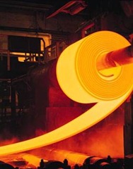
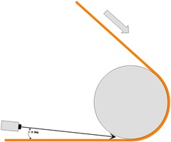
A technique called the Wedge Method or Roll Nip method is finding increased use in measuring strip temperatures in the metal production/processing industries as it is touted as providing the dual advantages of appearing to be independent of the material emissivity and the presence of any ambient reflected radiation. Basically, the concept is quite simple: Picture a horizontal steel strip that contacts and at least partially wraps around a large roll, usually a deflector roll used to change strip direction or a bridle roll used to set strip tension. Aim a radiation thermometer almost parallel to the strip into the gap formed between the roll and strip tangent point, as deep as you can go. (Viewing at an angle from the side is fine). This gap, as the claims state, can be treated as a blackbody with an emissivity of 1.0 (see Figure 1). Hence, you don’t have to worry about ambient radiation as reflectivity is 0.0 and you don’t have to worry about changing material emissivity. This is partly true and partly wishful thinking.
Blackbody conditions exist for a cavity if and only if all sides of the cavity are at the same temperature. If the roll being used has a very low thermal mass (heats up easily) and there is a large wrap around the roll and sufficient strip tension to allow heat transfer to occur between the strip and the roll, then the roll will heat up to near strip temperature over a time period, but because the roll has natural convection, conduction and radiation losses, the roll can never quite reach the strip temperature. Emissivity never reaches 1.0. It should be obvious that if the strip abruptly changes temperature, which can happen with strip thickness or furnace temperature changes, it will take time for the roll to change temperatures. Heat transfer between the two can take quite a while during which time the temperature reading from the wedge system will be quite inaccurate.
So, if a system is designed well, with a major roll wrap, low thermal mass roll, sufficient strip tension and steady long term operation (no major changes in strip temperature), this method can work as claimed (except that emissivity must be set somewhat lower than 1.0 to compensate for the roll being at a slightly lower temperature than the strip).
Given human nature, however, I’ve seen numerous instances where folks have not understood why the wedge method can work and who have misapplied it. Believe it or not, I’ve seen an instance where a so-called wedge method has been applied with zero roll wrap, with the strip simply passing over a support roll. And this system was (unfortunately) designed by the equipment provider who should have known better. I would guess that a majority of wedge method applications that I’ve seen have been poorly designed, with little attention paid to the amount of roll wrap or roll material and with little understanding of what occurs during changes in strip temperature.
There is a modification to the wedge method that can provide a significant improvement: Mount a second Radiation Thermometer to monitor roll temperature and compare this reading to that of the wedge RT. Using a PC with input and output cards (and most any older PC will work), abrupt deviations between the two readings which occur as strip temperature changes can be used to correct for errors. If accuracy is desired, it’s well worth the extra expense. You get what you pay for.
Wednesday, September 27, 2017
Furnace and Heater Tube Inspections
Process Heaters
There are as many uses for process heaters as there are designs. The basic configuration consists of a shell (outer casing), tubes (where the process fluid flows) and a heat source. These units are both thermodynamically and hydraulically complex.
The simple drawing illustrates convective gas flow, which is turbulent, and radiant heat from the flame, refractory and other tubes – all non-uniform and time varying. When you view tube from an access port typically you can only see a portion of the tube or the tube at an oblique angle. Sometimes tubes are in rows, difficult if not impossible to image.
Why are heater tubes of interest anyway?
![]() |
| Tubes in a fired heater |
Sample Thermal Images
![]() |
| Tube with restricted flow |
![]() |
| Coking on bottom of tube |
IR offers the operators of process heaters the ability to visualize the heat transfer and provide vital temperature data to help determine remaining tube life. Certification training from the Infrared Training Center (http://www.infraredtraining.com) teaches you the techniques required to successfully implement this technology at your facility.
Thermography Certification Dates and Locations
- Training Dates and Locations in the US and Canada: http://www.infraredtraining.com/schedule
- Training Dates and Locations in Europe, Middle East and Africa: http://www.irtraining.eu
To learn more about these certification classes, as well as upcoming training dates and locations, please visit the Infrared Training Center online at http://www.infraredtraining.com
Wednesday, August 27, 2014
New Online Course - Emissivity Explained in Plain English
At the conclusion of this course, learners will be able to:
- Explain the basic nature of Emissivity
- Describe its importance for image interpretation and measurement
- Identify a few high and low emissivity surfaces
Friday, November 15, 2013
Emissivity Explained; In Plain English
Wednesday, February 29, 2012
About Emissivity Tables
Emissivity tables may or may not contain real useful information concerning the actual emissivities of the objects you wish to measure.
There can be many variations within and among different emissivity tables. Here are some factors of concern:
- Total Normal (broadband, perpendicular) emissivity - This is the emissivity over a very wide waveband. It may or may not be close to the actual emissivity with respect to your infrared camera.
- Midwave emissivity - Some tables are listed as shortwave (now called midwave) or at a specific narrow short waveband. Even if the emissivity is specified to be within the same spectral waveband as your infrared camera, it still may not be as accurate as you suspect. This is due to differences in camera detector responses.
- Longwave emissivity - Longwave tables can also be somewhat unreliable for the same reasons described for the shortwave. Older cameras used different detectors that had different responses within the long wave band.
- Narrow waveband - A narrow band can be just as unreliable as a wide band. Some materials can have significant changes in emissivity over small wavebands.
- Temperature - Some tables take into account the temperature of the object when the emissivity was measured. If you consider the previously mentioned variables, this does not necessarily make the tables any more reliable.
- Conditional (rough, smooth, corroded, rusty) - Conditional parameters seem to offer useful information concerning emissivities, but it is sometimes quite difficult to ascertain the condition of a metal surface by looking at it. If you use an emissivity table to determine the emissivity of copper, you may find values ranging from 0.05 to 0.86, depending on the surface. Copper that appears to be very tarnished can still have an extremely low emissivity.
So, what is one to do regarding emissivity tables? First, realize their limitations. They can offer a ball park estimate. If you really would like to use emissivity tables, the best thing to do is to create your own based on measurements taken with your camera.
Click this link for instructions on how to measure emissivity.
Thursday, February 23, 2012
Accuracy Specification of FLIR Cameras
How accurately can the camera measure an absolute temperature?
Most FLIR Thermography cameras have a specified accuracy of ±2 ºC (±3.6 ºF) or ±2% (whichever is greater) of reading for a blackbody target (emissivity ~ 1).
For example, for objects that are 100 °C or lower, the temperature reading off a blackbody can be 98°C to 102°C and be within specification. Similarly for objects above 100°C, say 200 °C, the reading could vary between 196°C and 204°C.
Some science cameras such as the SC660 are specified ±1°C or ±1% of reading.
This means that any camera, at any environment condition (within specification), at any time will give a reading within the accuracy specification.
However, a particular camera, at the same environment condition, will have a statistical repeatability of measurement that is much better than this. Typically close to the NETD value. This is also applicable when you compare adjacent pixels, provided your target(s) are optically resolved. This means that much higher accuracies can be achieved by comparing values with a known reference source in the image scene.
Friday, December 9, 2011
Stainless steel reflecting sky temp
This is extracted from a recent message board post:
"I'm curious as to how to adjust for stainless steel reflecting sky temp. The apparent reflected temp of the ground and surroundings is approx 50F. The bottom half of the drum is reflecting this (SP4). The top half is reflecting the sky (SP5).
In my software, if I set the emissivity to 1, the sky temp in the picture shows -34F.
SP4 and SP5 *should* be the same temp, within a few degrees, based on the operation of the equipment. If I enter 50F as RAT for SP4, I have to enter -95F as RAT for SP5 to get the two temperatures to match.
Why is it -95F and not -34F for SP5? I want to make sure I'm understanding and looking at the image correctly. "
Monday, November 7, 2011
Using Cavities to Solve Emissivity Problems, Here's the Drill
by Bernie Lyon
Here are two illustrations that I have created to demonstrate how the cavity effect works.
Referring to Figure 1, the “ideal” block has an emissivity of 0.2 and a reflectivity of 0.8 We are assuming that these values are constant and do not change with angle. This is not the case. If thermal radiation strikes a single surface, 20% of the radiation is absorbed and 80% is reflected. (Keep in mind 20% of the radiation – Not the temperature!) If it strikes another surface before exiting, 20% of what remains is absorbed and 80% of that is reflected, and so on.
Therefore, with multiple reflections caused by cavities, the effective emissivity, or emittance, increases, while the effective reflectivity decreases. This is the reason why holes and cavities appear dark. They reflect less visible light.
Wednesday, October 14, 2009
How Emissivity affects Heat Transfer and Surface Temperature
"I know the higher the emissivity a surface has the greater its ability to absorb heat (IR), however, is a painted surface able to reject or shed heat better? An example would be does a painted engine run cooler than a unpainted metal engine or hotter or the same temp?"
If an object has a higher temperature than its environment, then increasing its emissivity will certainly lower its temperature. As an example, lets look at the motor in the illustration. It has a cover made of stainless steel and is very shiny. Let's assume its emissivity is 0.1. We have measured its steady state temperature at 150 F. The rate of heat generation of the motor has to be exactly balanced by the rate of heat loss from the motor. So, in this case for simplification, we will only consider convection and radiation. The numbers are shown in the illustration.
Wednesday, September 30, 2009
Quick and Easy Solution to Emissivity Problems
"We've received the camera and so far it's been good in that department. I am concerned however about emissivity. In my application, I'm filming the inside of a computer system which is a small, tightly packed space with different materials and emissivities. Because thermography is something new to me, I'm not sure how much of a role emissivity plays in throwing off my measurements. I could attach a thermocouple to each component to verify the readings on the thermal cam, however that's very time consuming and given the limited amount of time I have with this instrument, it doesn't make sense. I've read that there's emissivity sprays that will help with this issue but don't know if that solution is any better or cost effective. Do you have any cheap and quick solutions for my problem?"
Yes, emissivity can play a big role in your temperature measurement accuracy, especially if you are trying to measure shiny metals. Here is what I would do:
Measure your reflected apparent temperature
- Set camera emissivity to 1.0
- Use some slightly crinkled aluminum foil and place next to your target(s).
- Using the area mode of your camera set to average temperature, read the apparent average temperature of the aluminum foil. (Be careful that you don't reflect your own heat reflection of the foil).
- Enter this temperature as the reflected temperature in your camera.
- Use some Liquid Paper brand correction fluid.
- Place a small amount on your targets.
- Set your camera emissivity to 0.95
- Measure the temperature of your target(s)
- When using these techniques make sure that the correction fluid will not damage your components.
- Use a small amount of correction fluid. Changing the emissivity of small shiny components from less than 0.1 to 0.95 will greatly affect the heat transfer from these components, and thus affect their temperature. So the smallest amount of emissivity improver that you can measure is the amount to use. This is easy on FLIR systems cameras, just make sure that the emissivity improver is large enough to fill the cursor circle on the spot tool. Anything smaller will not be measured correctly.
- There are more sophisticated ways of doing this automatically for all materials on a PCB through software. Please contact a FLIR Systems Scientific Segment Engineer regarding Altair software.
- If you don't understand emissivity and reflected apparent temperature terms, get some training! A good place to start is this web based course, Thermography Basics.