Here’s a video with Tom O’toole of FLIR Systems and Flemming Lund, a certified Energy Auditor & Home Inspector, talking about the tools used in the various phases involved in a home energy audit.
Infrared Training Center

Wednesday, January 10, 2018
FLIR Home Energy Audit Tools
What tools do Home Energy Auditors and Home Inspectors use? Shopping for
the right Home Energy Auditor or Home Inspector can be a timely
process. Beyond their certifications and experience, you should also
consider the types of tools they use to perform their tasks.
Here’s a video with Tom O’toole of FLIR Systems and Flemming Lund, a certified Energy Auditor & Home Inspector, talking about the tools used in the various phases involved in a home energy audit.
Here’s a video with Tom O’toole of FLIR Systems and Flemming Lund, a certified Energy Auditor & Home Inspector, talking about the tools used in the various phases involved in a home energy audit.


Thursday, January 4, 2018
Cost Avoidance/Energy Savings for IR Thermography
"Has anyone documented Cost Avoidance Or Potential energy savings using Thermography. Ex. Downtime, Labor, Materials. I would be interested in understanding how you determined final cost or energy savings."
This is the $64,000 question, how to justify the cost and benefits of an IR program. The methods used vary depending on your situation, what downtime costs in your facility, overtime and rush ordering to get new parts, lost production cost, your energy cost, etc.
I have selected several white papers that illustrate how different organizations have calculated their costs. Use them as examples of what can be done, and how they are presented.
Use this link to download the files.
Wednesday, December 20, 2017
InfraMation 2018 - Call for Papers and Abstracts
 InfraMation 2018 will be held in Austin, Texas, September 11-14, 2018 and we are thrilled to be heading to the "Live Music Capital of the World". Austin is known for its vibrant buzzing energy, never-ending entertainment options, and stunning outdoor settings. One thing is for sure, we will be ready to paint the town InfraRED! Join other thermal imaging experts to learn the latest thermal imaging techniques and applications, and make valuable connections!
Hilton Austin has been chosen as the InfraMation 2018 host hotel. Hilton Austin is situated right in downtown Austin, TX, just a quick walk from exclusive shopping, amazing restaurants, and a multitude of live music venues on 6th Street and the surrounding area. InfraMation attendees receive a deeply discounted rate of $199/night plus taxes. Based on availability, this incredible rate can be extended 3 days post or prior if you'd like to stay a bit longer!
Submit your abstract through this simple online form.
Benefits & Requirements - Why should you present at InfraMation 2018?
- Qualify for a deeply discounted conference registration fee
- Identify yourself as an infrared thermal imaging expert in your field
- Earn valuable certification renewal credit
- Further validate your expertise for clients and customers
- Expand your professional and business referral network
- Represent your organization on a big stage
Suggested Topic Areas
- Buildings
- Roofing Systems
- Water Ingress / Moisture / Remediation / Mold Testing
- Insulation / Air Leakage / Energy Loss
- Standards & Certification
- Pest Detection and Control
- Condition Monitoring
- Electrical Distribution - Indoor, Outdoor, Transmission, Distribution
- Mechanical Applications - Bearings, Gearboxes, Conveyors, Steam,
- Hydraulic
- Standards & Certification
- Petrochemical Applications
- Business
- Marketing/Sales/Pricing
- Program Management / Cost Avoidance / Cost Saving
- Safety
- Research & Science Applications
- Medical/Veterinary Applications
- Optical Gas Imaging Applications
- IR Report Preparation Techniques
- Aerial Drone and UAV Applications / Techniques
- Public Safety
- Non-Destructive Testing - Material flaws, voids, etc.
- Alternative / other Applications / Other Technologies
What the heck is Emissivity? (Part 2)

Infrared Training Center
Friday, December 8, 2017
What the Heck is Emissivity? (part 1)

Thursday, November 16, 2017
It is Not Always about Loose Contacts
by Ahmed Osman Mohamed Hamoudy
Electrical PM & PdM Engineer
Cemex, Egypt
In modern industries, there are many predictive maintenance techniques that can be utilized to avoid an unexpected failure. At CEMEX, we count on those techniques and deploy them in such a way as to get the most use from it, and avoid any undesirable consequences. IR thermography's use has become widespread in cement plants; application areas typically include rotating kilns, insulation, mechanical, and electrical systems.
This article will explore the uses of IR thermography, specifically as part of the Motor Control Center systems predictive maintenance routine, including typical electrical panel failure points (contactor, terminations, feeding breaker, fuses, cables, etc...).
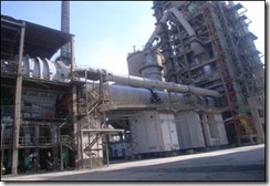
Figure 1. Rotary Kiln
One of the Clinker Rotary Kilns (4,500 Tons per Day) is supposed to be available for operation not less than a year, which is a challenge of course, to guarantee continuous operation for the kiln system for this time without any unexpected shutdown.
Monday, November 13, 2017
Emissivity and Reflected Temperature
What should I enter for my emissivity and reflected temperature values?
First, ask yourself how are you using your thermal imager? Is it to identify thermal patterns or measure temperatures? If you are simply trying to locate thermal patterns such as missing insulation or air leakage in a building (what is called qualitative thermography) measuring an exact temperature really isn’t necessary. In these situations, leave the values at their default settings (typically 0.95 for emissivity and 68F/20C for reflected temperature) and go for it.
If you need to measure an exact temperature of a motor or a bearing (what is called quantitative thermography) then correctly setting emissivity and reflected temperature is a must to get the most accurate reading. Doing so, however, should only be attempted by properly trained and certified thermographers…those who are the most qualified to measure temperatures with an infrared camera.
Thermography Certification Dates and Locations
What Is the Best Approach Until Then?
We recommend using the following basic guideline for taking simple measurements. Know there are many other factors you will need to consider which are covered thoroughly in all ITC training classes. Until then, to get started, let’s first define emissivity and reflected temperature.
What is Emissivity?
Emissivity is how efficiently an object radiates heat. It’s defined as the ratio of infrared energy emitted by the object, compared to that emitted by an ideal blackbody, if both are at the same temperature. It is represented as either a percent or a decimal.
Surfaces exhibit emissivity values ranging anywhere from 0.01 to 0.99. A highly polished metallic surface such as copper or aluminum are often below 0.10 and are practically an infrared mirror. Heavily oxidized metallic surfaces will have a much higher emissivity (0.6 or greater depending on the surface condition and the amount of oxidation). Most flat-finish paints are around 0.90 (in long-wave infrared) while human skin and water are about 0.98.
What is Reflected Temperature?
Reflected temperature (also known as background temperature or Treflected) is any thermal radiation originating from other objects that reflects off the target you are measuring. To properly obtain an accurate surface temperature reading with thermal imaging, this value (along with that of emissivity) must be quantified and programmed into the camera’s “Object Parameters” (or corresponding software if processing a saved image). This is used so that the software can compensate for, and ignore, the effects of this radiation as it does not relate to the actual surface temperature of the object you are measuring.
For higher emissivity objects, reflected temperature has less influence. For lower emissivity objects, however, it’s a critical factor that *must be* understood carefully! As emissivity decreases, what you are measuring (and seeing thermally) is coming more from the surfaces of surrounding objects (including the camera and operator), not the target you are inspecting.
How to Take a Basic Temperature Measurement
The easiest way to get an accurate measurement is to modify the surface with a material that has a high, known, and consistent emissivity value. Standard electrical tape, with its emissivity of .95, is one such item that works well for this purpose.
If the surface is safe to touch, simply adhere a piece of electrical tape to that object and set the camera’s emissivity value to 0.95. Next set the reflected temperature to an appropriate value for the environment. A stable, room temperature environment will provide the best results. If you’re still unsure what that value might be, we strongly suggest a minimum of Level I Certification training to understand this concept further.
Next, measure the temperature of the tape with the camera’s spot meter or other measurement tool, being sure that the spot meter’s circle (called the reticle) is filled completely by the target. IMPORTANT SAFETY NOTE: This “tape method” should *only be utilized* on stationary surfaces that can be accessed safely and are okay to touch. If attempting this type of measurement on an electrical component, the circuit *must* first be shut off and locked-out/tagged-out before proceeding.
What About Measuring Emissivity and Reflected Temperature on Other Surface Types?
For other surface types, or if temperature measurement accuracy on a variety of other objects is important for you and your inspection program, a minimum of a Level I Thermography Certification Training course is required. Level I will teach you how to correctly adjust emissivity and reflected temperature on a variety of other components including those that are electrically energized or are difficult to access. Attendees will learn about the proper procedures needed to evaluate both to ensure thermographers are getting the most accurate temperature readings with their thermal imager.
To learn more about these certification classes, as well as upcoming training dates and locations, please visit the Infrared Training Center online at http://www.infraredtraining.com
First, ask yourself how are you using your thermal imager? Is it to identify thermal patterns or measure temperatures? If you are simply trying to locate thermal patterns such as missing insulation or air leakage in a building (what is called qualitative thermography) measuring an exact temperature really isn’t necessary. In these situations, leave the values at their default settings (typically 0.95 for emissivity and 68F/20C for reflected temperature) and go for it.
If you need to measure an exact temperature of a motor or a bearing (what is called quantitative thermography) then correctly setting emissivity and reflected temperature is a must to get the most accurate reading. Doing so, however, should only be attempted by properly trained and certified thermographers…those who are the most qualified to measure temperatures with an infrared camera.
Thermography Certification Dates and Locations
- Training Dates and Locations in the US and Canada: http://www.infraredtraining.com/schedule
- Training Dates and Locations in Europe, Middle East and Africa: http://www.irtraining.eu
- Certification training from the Infrared Training Center (http://www.infraredtraining.com) teaches you the techniques required for determining these values and will provide a complete understanding of temperature measurement and heat transfer.
What Is the Best Approach Until Then?
We recommend using the following basic guideline for taking simple measurements. Know there are many other factors you will need to consider which are covered thoroughly in all ITC training classes. Until then, to get started, let’s first define emissivity and reflected temperature.
What is Emissivity?
Emissivity is how efficiently an object radiates heat. It’s defined as the ratio of infrared energy emitted by the object, compared to that emitted by an ideal blackbody, if both are at the same temperature. It is represented as either a percent or a decimal.
Surfaces exhibit emissivity values ranging anywhere from 0.01 to 0.99. A highly polished metallic surface such as copper or aluminum are often below 0.10 and are practically an infrared mirror. Heavily oxidized metallic surfaces will have a much higher emissivity (0.6 or greater depending on the surface condition and the amount of oxidation). Most flat-finish paints are around 0.90 (in long-wave infrared) while human skin and water are about 0.98.
What is Reflected Temperature?
Reflected temperature (also known as background temperature or Treflected) is any thermal radiation originating from other objects that reflects off the target you are measuring. To properly obtain an accurate surface temperature reading with thermal imaging, this value (along with that of emissivity) must be quantified and programmed into the camera’s “Object Parameters” (or corresponding software if processing a saved image). This is used so that the software can compensate for, and ignore, the effects of this radiation as it does not relate to the actual surface temperature of the object you are measuring.
For higher emissivity objects, reflected temperature has less influence. For lower emissivity objects, however, it’s a critical factor that *must be* understood carefully! As emissivity decreases, what you are measuring (and seeing thermally) is coming more from the surfaces of surrounding objects (including the camera and operator), not the target you are inspecting.
How to Take a Basic Temperature Measurement
The easiest way to get an accurate measurement is to modify the surface with a material that has a high, known, and consistent emissivity value. Standard electrical tape, with its emissivity of .95, is one such item that works well for this purpose.
If the surface is safe to touch, simply adhere a piece of electrical tape to that object and set the camera’s emissivity value to 0.95. Next set the reflected temperature to an appropriate value for the environment. A stable, room temperature environment will provide the best results. If you’re still unsure what that value might be, we strongly suggest a minimum of Level I Certification training to understand this concept further.
Next, measure the temperature of the tape with the camera’s spot meter or other measurement tool, being sure that the spot meter’s circle (called the reticle) is filled completely by the target. IMPORTANT SAFETY NOTE: This “tape method” should *only be utilized* on stationary surfaces that can be accessed safely and are okay to touch. If attempting this type of measurement on an electrical component, the circuit *must* first be shut off and locked-out/tagged-out before proceeding.
What About Measuring Emissivity and Reflected Temperature on Other Surface Types?
For other surface types, or if temperature measurement accuracy on a variety of other objects is important for you and your inspection program, a minimum of a Level I Thermography Certification Training course is required. Level I will teach you how to correctly adjust emissivity and reflected temperature on a variety of other components including those that are electrically energized or are difficult to access. Attendees will learn about the proper procedures needed to evaluate both to ensure thermographers are getting the most accurate temperature readings with their thermal imager.
To learn more about these certification classes, as well as upcoming training dates and locations, please visit the Infrared Training Center online at http://www.infraredtraining.com
Thursday, October 26, 2017
Windshield Glass Reflections - How to Remove Them
by Bernie Lyon, Gary Orlove, and Jason Gagnon
"I do a lot of windshield defrost testing at different temps. And I wonder is there any way that can keep from having the camera and myself reflected back into the images."
Glass is about 15% reflective in the 8-12 micrometer waveband. If you are directly facing the windshield, you will inevitably get a reflection of yourself and the camera. I'm sure you have seen this.
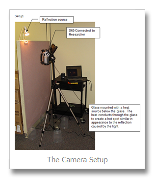
One option is to change the angle at which you are observing the windshield, see the image below. If you are at point A, you and the camera will be reflected. If you are at point B, the camera will reflect whatever is above the vehicle, represented by C.

If there are hot objects or objects with temperature variations above the vehicle, that might make things worse. They will reflect off of the glass. If possible, you could place a high emissivity piece of material above the windshield so that all reflections off of the glass are uniform. A large piece of cardboard or a blanket might do well.
This way, you will observe only temperature changes, not patterns due to non-uniform reflections.
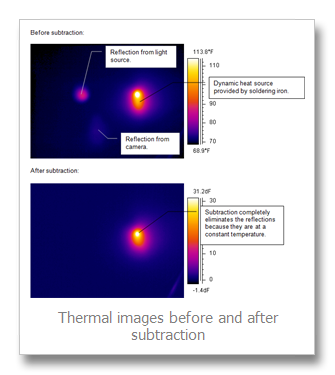
Another option is to use image subtraction techniques (you will have to have software which supports this, such as FLIR ThermaCAM Researcher).
- Take an image before running the defroster.
- Then save images as you normally would.
- Subtract the first image from the succeeding ones. The resulting image will show only changes in temperature and the reflections will have been eliminated. See the series of images below:

Wednesday, October 18, 2017
New Online Course - Basics of Fluke SmartView® Software
New from the Infrared Training Center, this tutorial will show you how to operate the essential features of Fluke SmartView® .
This course is also for ITC-trained thermographers with Fluke thermal imagers who require guidance on using the software to complete the Field Assignment portion of their infrared certification.
After taking this course, learners will be able to:
This course is also for ITC-trained thermographers with Fluke thermal imagers who require guidance on using the software to complete the Field Assignment portion of their infrared certification.
After taking this course, learners will be able to:
- Launch and set-up Fluke SmartView®
- Perform basic thermal image editing and analysis
- Configure the Quick Report settings
- Output a basic infrared report using the Quick Report feature
- Draw attention with a heading.
Thursday, October 12, 2017
Use of the Wedge Method for Emissivity and Reflection Independent Temperature Measurement
By: Ralph Rudolph
R. Rudolph Consulting LLC @ www.temperatureconsultant.com
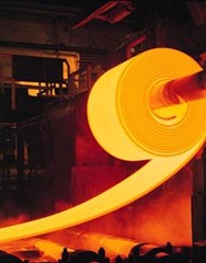
Blackbody conditions exist for a cavity if and only if all sides of the cavity are at the same temperature. If the roll being used has a very low thermal mass (heats up easily) and there is a large wrap around the roll and sufficient strip tension to allow heat transfer to occur between the strip and the roll, then the roll will heat up to near strip temperature over a time period, but because the roll has natural convection, conduction and radiation losses, the roll can never quite reach the strip temperature. Emissivity never reaches 1.0. It should be obvious that if the strip abruptly changes temperature, which can happen with strip thickness or furnace temperature changes, it will take time for the roll to change temperatures. Heat transfer between the two can take quite a while during which time the temperature reading from the wedge system will be quite inaccurate.
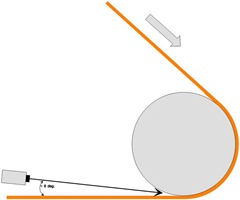
Figure 1.
So, if a system is designed well, with a major roll wrap, low thermal mass roll, sufficient strip tension and steady long term operation (no major changes in strip temperature), this method can work as claimed (except that emissivity must be set somewhat lower than 1.0 to compensate for the roll being at a slightly lower temperature than the strip).
Given human nature, however, I’ve seen numerous instances where folks have not understood why the wedge method can work and who have misapplied it. Believe it or not, I’ve seen an instance where a so-called wedge method has been applied with zero roll wrap, with the strip simply passing over a support roll. And this system was (unfortunately) designed by the equipment provider who should have known better. I would guess that a majority of wedge method applications that I’ve seen have been poorly designed, with little attention paid to the amount of roll wrap or roll material and with little understanding of what occurs during changes in strip temperature.
There is a modification to the wedge method that can provide a significant improvement: Mount a second Radiation Thermometer to monitor roll temperature and compare this reading to that of the wedge RT. Using a PC with input and output cards (and most any older PC will work), abrupt deviations between the two readings which occur as strip temperature changes can be used to correct for errors. If accuracy is desired, it’s well worth the extra expense. You get what you pay for.
Subscribe to:
Posts (Atom)