Infrared Training Center

Showing posts with label infrared camera. Show all posts

Wednesday, March 7, 2018

Less Expensive Thermal Imagers Never Meant Less Training

Matt Schwoegler, ITC

When I first started training thermographers back in 2002, most infrared cameras at the time were $40,000-60,000 USD.  It was a significant investment for many organizations who were using thermography which they took very seriously.  They took training seriously too.  After all, if you’re spending that much money on a piece of hardware, the operator better know how to use it properly.

It was shortly after that the world’s first sub-$10,000 thermal imager made its debut with a price point that changed the industry.  Today you can buy an IR camera that fits on your phone for just a few hundred dollars and the variety and quality of what’s available for under $10,000 is simply astonishing.   

What hasn’t changed in that time is physics.  Heat still moves from hot to cold.  Unfortunately, just like the cost of equipment, the conversation between the employee and the employer about the need and expense of training has seemingly changed.

Fifteen years ago, after spending $50,000+ on a new camera, I’d bet most didn’t put too much thought into the additional cost of training.  There was absolutely no question…with an investment that large, you better know what you’re doing! The response from a supervisor when asked by a thermographer for approval to attend a class was often similar to this:

Wednesday, February 28, 2018

FLIR ONE Online Training

FLIR ONE Basics
This course will introduce you to the operation of the FLIR ONE and FLIR ONE Pro infrared camera. This course is a self paced on-demand web course, you can start as soon as you enroll and you can stop and continue where you left off at any time. There is NO CHARGE for this course.

Friday, January 26, 2018

Lens Choice for Looking Through IR Windows

by Gary Orlove
More and more organizations are installing IR windows or sight glasses in their electrical equipment so inspections can be made with an infrared camera.
The advantages are obvious: worker safety is improved as thermographers and electricians don't have to open live electrical cabinets, and inspection times can be reduced.
However, what lens choice is the best to use with your infrared camera to provide adequate resolution, and yet see as much of the electrical equipment as possible?
Here are three images that were taken at a power plant looking at an ISO phase buss. The buss is only about a foot away and is taken looking through an infrared window (crystal type).
25 deg.
45 deg.
90 deg.
Images courtesy - John Fricot, FLIR Systems
As you can plainly see, the 90° lens is clearly the way to go.  It provides enough detail for analysis, yet extends your field of view by a huge amount.

Thursday, January 4, 2018

Cost Avoidance/Energy Savings for IR Thermography

"Has anyone documented Cost Avoidance Or Potential energy savings using Thermography. Ex. Downtime, Labor, Materials. I would be interested in understanding how you determined final cost or energy savings."

This is the $64,000 question, how to justify the cost and benefits of an IR program. The methods used vary depending on your situation, what downtime costs in your facility, overtime and rush ordering to get new parts, lost production cost, your energy cost, etc.

I have selected several white papers that illustrate how different organizations have calculated their costs. Use them as examples of what can be done, and how they are presented.

Use this link to download the files.

Wednesday, December 20, 2017

InfraMation 2018 - Call for Papers and Abstracts

inframation2018-logoInfraMation 2018 will be held in Austin, Texas, September 11-14, 2018 and we are thrilled to be heading to the "Live Music Capital of the World". Austin is known for its vibrant buzzing energy, never-ending entertainment options, and stunning outdoor settings. One thing is for sure, we will be ready to paint the town InfraRED! Join other thermal imaging experts to learn the latest thermal imaging techniques and applications, and make valuable connections!

Hilton Austin has been chosen as the InfraMation 2018 host hotel. Hilton Austin is situated right in downtown Austin, TX, just a quick walk from exclusive shopping, amazing restaurants, and a multitude of live music venues on 6th Street and the surrounding area. InfraMation attendees receive a deeply discounted rate of $199/night plus taxes. Based on availability, this incredible rate can be extended 3 days post or prior if you'd like to stay a bit longer!

Submit your abstract through this simple online form.

Benefits & Requirements - Why should you present at InfraMation 2018?
  • Qualify for a deeply discounted conference registration fee
  • Identify yourself as an infrared thermal imaging expert in your field
  • Earn valuable certification renewal credit
  • Further validate your expertise for clients and customers
  • Expand your professional and business referral network
  • Represent your organization on a big stage
Publish your paper on a searchable CD that every InfraMation attendee receives. InfraMation is the leading infrared training experience in the world. As thermal imaging becomes more mainstream, early adopters such as yourself will be sought out for your extensive know how and experience. Simply put: InfraMation is the place to get recognized! The only "hard" requirements are that your paper be non-commercial in nature (for sponsorship or exhibition opportunities, click here) and submitted in English. Abstract approval is based on clarity, suitability, and technical merit of work.

Suggested Topic Areas
  • Buildings
    • Roofing Systems
    • Water Ingress / Moisture / Remediation / Mold Testing
    • Insulation / Air Leakage / Energy Loss
    • Standards & Certification
    • Pest Detection and Control
  • Condition Monitoring
    • Electrical Distribution - Indoor, Outdoor, Transmission, Distribution
    • Mechanical Applications - Bearings, Gearboxes, Conveyors, Steam,
    • Hydraulic
    • Standards & Certification
    • Petrochemical Applications
  • Business
    • Marketing/Sales/Pricing
    • Program Management / Cost Avoidance / Cost Saving
    • Safety
  • Research & Science Applications
  • Medical/Veterinary Applications
  • Optical Gas Imaging Applications
  • IR Report Preparation Techniques
  • Aerial Drone and UAV Applications / Techniques
  • Public Safety
  • Non-Destructive Testing - Material flaws, voids, etc.
  • Alternative / other Applications / Other Technologies


What the heck is Emissivity? (Part 2)


Fill up two soda cans with hot water and wrap one in scotch tape. Which one will cool down faster? Obvious, right? Check it out, you might be surprised!


Infrared Training Center

Thursday, November 16, 2017

It is Not Always about Loose Contacts

by Ahmed Osman Mohamed Hamoudy
Electrical PM & PdM Engineer
Cemex, Egypt

In modern industries, there are many predictive maintenance techniques that can be utilized to avoid an unexpected failure. At CEMEX,  we count on those techniques and deploy them in such a way as to get the most use from it, and avoid any undesirable consequences. IR thermography's use has become widespread in cement plants; application areas typically include rotating kilns, insulation, mechanical, and electrical systems.

This article will explore the uses of IR thermography, specifically as part of the Motor Control Center systems predictive maintenance routine, including typical electrical panel failure points (contactor, terminations, feeding breaker, fuses, cables, etc...).

clip_image002
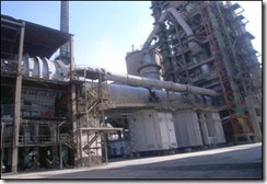
Figure 1. Rotary Kiln

One of the Clinker Rotary Kilns (4,500 Tons per Day) is supposed to be available for operation not less than a year, which is a challenge of course, to guarantee continuous operation for the kiln system for this time without any unexpected shutdown.

Thursday, October 26, 2017

Windshield Glass Reflections - How to Remove Them

by Bernie Lyon, Gary Orlove, and Jason Gagnon

"I do a lot of windshield defrost testing at different temps. And I wonder is there any way that can keep from having the camera and myself reflected back into the images."

Glass is about 15% reflective in the 8-12 micrometer waveband. If you are directly facing the windshield, you will inevitably get a reflection of yourself and the camera. I'm sure you have seen this.

One option is to change the angle at which you are observing the windshield, see the image below. If you are at point A, you and the camera will be reflected. If you are at point B, the camera will reflect whatever is above the vehicle, represented by C.

image

If there are hot objects or objects with temperature variations above the vehicle, that might make things worse. They will reflect off of the glass. If possible, you could place a high emissivity piece of material above the windshield so that all reflections off of the glass are uniform. A large piece of cardboard or a blanket might do well.

This way, you will observe only temperature changes, not patterns due to non-uniform reflections.

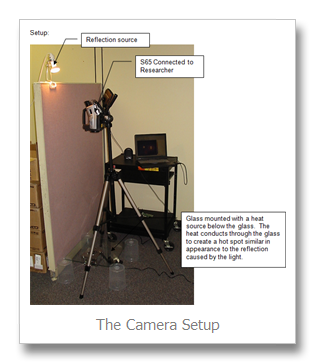
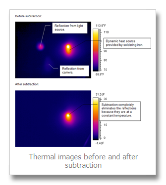
Another option is to use image subtraction techniques (you will have to have software which supports this, such as FLIR ThermaCAM Researcher).

  1. Take an image before running the defroster.
  2. Then save images as you normally would.
  3. Subtract the first image from the succeeding ones. The resulting image will show only changes in temperature and the reflections will have been eliminated. See the series of images below:

Thursday, October 12, 2017

Use of the Wedge Method for Emissivity and Reflection Independent Temperature Measurement

By: Ralph Rudolph
R. Rudolph Consulting LLC @
www.temperatureconsultant.com
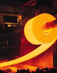
clip_image002A technique called the Wedge Method or Roll Nip method is finding increased use in measuring strip temperatures in the metal production/processing industries as it is touted as providing the dual advantages of appearing to be independent of the material emissivity and the presence of any ambient reflected radiation. Basically, the concept is quite simple: Picture a horizontal steel strip that contacts and at least partially wraps around a large roll, usually a deflector roll used to change strip direction or a bridle roll used to set strip tension. Aim a radiation thermometer almost parallel to the strip into the gap formed between the roll and strip tangent point, as deep as you can go. (Viewing at an angle from the side is fine). This gap, as the claims state, can be treated as a blackbody with an emissivity of 1.0 (see Figure 1). Hence, you don’t have to worry about ambient radiation as reflectivity is 0.0 and you don’t have to worry about changing material emissivity. This is partly true and partly wishful thinking.

Blackbody conditions exist for a cavity if and only if all sides of the cavity are at the same temperature. If the roll being used has a very low thermal mass (heats up easily) and there is a large wrap around the roll and sufficient strip tension to allow heat transfer to occur between the strip and the roll, then the roll will heat up to near strip temperature over a time period, but because the roll has natural convection, conduction and radiation losses, the roll can never quite reach the strip temperature. Emissivity never reaches 1.0. It should be obvious that if the strip abruptly changes temperature, which can happen with strip thickness or furnace temperature changes, it will take time for the roll to change temperatures. Heat transfer between the two can take quite a while during which time the temperature reading from the wedge system will be quite inaccurate.
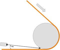
Wedge or cavity measurement method
Figure 1.

So, if a system is designed well, with a major roll wrap, low thermal mass roll, sufficient strip tension and steady long term operation (no major changes in strip temperature), this method can work as claimed (except that emissivity must be set somewhat lower than 1.0 to compensate for the roll being at a slightly lower temperature than the strip).

Given human nature, however, I’ve seen numerous instances where folks have not understood why the wedge method can work and who have misapplied it. Believe it or not, I’ve seen an instance where a so-called wedge method has been applied with zero roll wrap, with the strip simply passing over a support roll. And this system was (unfortunately) designed by the equipment provider who should have known better. I would guess that a majority of wedge method applications that I’ve seen have been poorly designed, with little attention paid to the amount of roll wrap or roll material and with little understanding of what occurs during changes in strip temperature.

There is a modification to the wedge method that can provide a significant improvement: Mount a second Radiation Thermometer to monitor roll temperature and compare this reading to that of the wedge RT. Using a PC with input and output cards (and most any older PC will work), abrupt deviations between the two readings which occur as strip temperature changes can be used to correct for errors. If accuracy is desired, it’s well worth the extra expense. You get what you pay for.

Wednesday, September 27, 2017

Furnace and Heater Tube Inspections

by Ron Lucier, ASNT NDT Level III
ITC logo registeredOne of the more challenging applications of infrared thermography is in the measurement of process heater and furnace tubes. In fact, we get dozens of inquiries each year from our clients on this very subject. Quantitative thermography is the practice of measuring temperatures accurately and with furnace tubes this requires experience and knowledge.  Success in this science is gained by being properly trained and certified as a Level I Furnace Inspection Thermographer. Certification training from the Infrared Training Center (http://www.infraredtraining.com) teaches you the techniques required for determining these values and will provide a complete understanding of temperature measurement and heat transfer.

Process Heaters
There are as many uses for process heaters as there are designs. The basic configuration consists of a shell (outer casing),   tubes (where the process fluid flows) and a heat source. These units are both thermodynamically and hydraulically complex.
Process heater or furnace diagram
The simple drawing illustrates convective gas flow, which is turbulent, and radiant heat from the flame, refractory and other tubes – all non-uniform and time varying. When you view tube from an access port typically you can only see a portion of the tube or the tube at an oblique angle. Sometimes tubes are in rows, difficult if not impossible to image.

Why are heater tubes of interest anyway?
Tubes in a fired heater
There are several reasons for inspecting tubes. Qualitatively scale buildup on the outside of the tube can be readily identified. Buildup on the inside of the tube (coking) is a bit more difficult but commonly performed. In both cases the scale or coke prevents the transfer of heat into the process fluid. In the case of scale buildup, the process fluid may not be sufficiently heated, affecting downstream processing. The case of coking on the inside of the tube is more serious. Since the coke has an increased resistance to heat transfer, the tube surface temperature increases. After all it is the flow of the process fluid that is keeping the tube “cool” in the first place. The external tube surface, unable to conduct its heat to the water, increases dramatically, causing a failure (opening) in the tube. Metallurgists use the measured temperature to calculate the life of the tube so accurate measurements are critical.

Sample Thermal Images
Tube with restricted flow
Coking on bottom of tube
Conclusion 
IR offers the operators of process heaters the ability to visualize the heat transfer and provide vital temperature data to help determine remaining tube life.  Certification training from the Infrared Training Center (http://www.infraredtraining.com) teaches you the techniques required to successfully implement this technology at your facility.

Thermography Certification Dates and Locations


To learn more about these certification classes, as well as upcoming training dates and locations, please visit the Infrared Training Center online at http://www.infraredtraining.com

Wednesday, September 20, 2017

Blower Door Inspection for Air Infiltration in a Remodeled Cottage

By Tom Coffey, Infrared Training Center 

ITC logo registeredA small cottage (700 sq. ft) outside of Knoxville, TN was completely remodeled from January to March 2010. It was an existing cinder block structure with no insulation except ½ inch of airspace between the nailers and the block wall as well as the empty block core. The R value of existing building walls was approximately 2.97. After the remodel an R-value was calculated and determined to be 12.6

2 x 4 studs were used to build the interior walls the insulated with 4” of backed fiberglass bat insulation. Old windows were removed and new double pane sash type windows installed during the remodel.

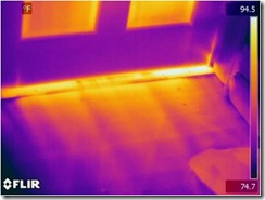
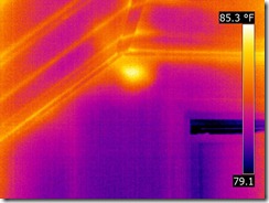
The house was depressurized to approximately 50 Pascal and allowed to equalize for 30 minutes. A thermographic scan was performed after the equalization period. Infiltration was found around the sash windows where the top and bottom pieces join in the corners of the windows.

Picture1 Picture2

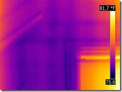
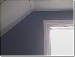
There was some expected infiltration around the front door which was missing a sweep on the bottom of the door. Also infiltration was found at the attic access.

Picture3 Picture4

All of these small problems are easily correctable and will be done as time permits.

The installation of the blower door took approximately 30-45 minutes. Reaching the right depressurization took another 30 minutes and the IR scan took another 45 minutes. For a house this size, allowing for the small footprint I did not do an air exchange calculation. The purpose of this exercise was to determine if the house remodel and adding insulation was sufficient to keep the house at a comfortable level during East Tennessee summers and winters. It was determined during the remodel process that R-13 insulation in the walls and R-19 insulation in the ceilings would be sufficient for the weather conditions in this area of the country.

Thursday, September 7, 2017

IR finds Yellow Jackets Nest in House

by Sanin Mulic, Barber Foods

After attending my level one instruction during the week, and ITC wetting my appetite for thermal imaging, I returned home with my company's P-65 camera.  I decided to scan my own house to practice what I was taught all week.  All looked good until I went upstairs and noticed a bright spot on the inside wall.  I took several images of the spot and come Monday, I talked to two level 2 associates about what I had found.  There were several possibilities and I was told to take several more shots at different times to see if it moved or varied in temperature.   When we found it never moved I suggested that it might be insects (wasps, hornets, etc.) and talked with one of the other thermographers who would bring in a stethoscope to see if  I could hear them before opening up the wall.

Wasps  Wasps-vis 
Thermal image of the wasp nest (left).

I couldn’t wait, so that night armed with a drill, a can of flying insect killer, and the enthusiasm of a new thermographer,  I went up to the room; my pet cat, who loves to lay in the window there, had to investigate with me too.   I approximated where the hotspot was and drilled a 1/8 “ hole through the wall board. As I removed the drill bit, about 8 to 10 yellow jackets came charging through the hole and I started to spray the bug spray at the hole.  By this time, the yellow jackets were in an attack mode and I started to swing at them in defense.  Out of the corner of my eye I saw my cat speeding to the door with his tail bigger than I have ever seen it.  I finally killed the last one, sprayed about 1/3 of the can, and plugged the hole; but not before being stung twice.  I went outside and saw a swarm just outside the window. I drilled a second hole a few inches above it and knowing what was going to follow,  I had the spray ready to go as soon as the drill came out.  I sprayed about 1/3 of the can and then plugged the hole. I returned several hours later and the swarm was gone.  I climbed a ladder and found a small hole where they were coming and going.  I plugged that from the outside.  As I came back inside I saw my cat peaking from around the door as if to ask “Is it safe to come out now?”

After a few days I took another thermal image and there was no evidence of the yellow jackets remaining.  I submitted this investigation as my level one field report and it passed, but the memory of this initial experience will last a long time (the cat won’t forget it either!)

No-wasps no-wasps-vis
No wasps after removal.

Tuesday, August 29, 2017

Why does my Infrared Camera read higher than my Infrared Temperature Gun?

 ITC Logo TM 250 The answer is, in a word, resolution. Take a look at the image below.

7-20-2010 1-48-44 PM

The infrared camera is able to locate and measure much smaller objects than an IR temperature gun. Note the spot measurement on the infrared image; its reading is 250 F. Contrast that to the average area measurement typical of an infrared gun at a reading of 184 F. The gun is averaging all the hot areas along with the cold areas of the grating we see in the image.

Another common question is why the IR camera reads a higher temperature than a contact temperature probe? Contact temperature probes require an extremely good contact in order to read a decent temperature. In fact these probes measure their own temperature, so if the heat transfer is not good from the substrate, and the probe sensor is colder than the surface, the temperature will be lower. Also remember that contact thermometers act as heat sinks, sucking heat out of a surface.

Wednesday, August 23, 2017

IR Pictures Through a Grating or Mesh

Question from a customer: “Scanning through the steel grating I read a temperature 5 to 15 degrees Celsius lower than scanning without the grating. I know it is to do with the steel grating but I was wondering why.”
Great question. Let’s take a look at a typical situation with and without a grating, and then placing the grating at different distances to the camera.
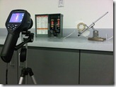
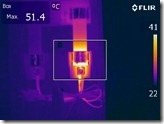
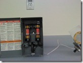
The distance between the fuse and the camera remains constant, and the camera is always focused on the fuse. The only changes are the insertion of the grating, and the distance of the grating from the infrared camera.
IMG00077-20120215-1115IR_0001DC_0002
Figure 1. Looking at a fuse directly with no grating. Max temperature is 51.4 C.
IMG00078-20120215-1116IR_0003DC_0004
Figure 2. We have inserted the grating close to the fuse.
Max temperature dropped to 51 C, a small error.

Wednesday, September 21, 2016

PUT YOUR MASK ON BEFORE HELPING OTHERS…

By Ronald D. Lucier, ASNT NDT Level III/TIR
Infrared Training Center
Nashua, NH  03063

Yes, another “Ron travel story!”

Those of us who travel react differently to the Flight Attendant Safety Instructions.  Some ignore them, some sleep through, the rare person actually pays attention and the multi-million miler has heard it thousands of times.  That doesn’t mean that we don’t listen still and take it seriously.  Many years ago I actually had a flight abort a takeoff and ended up going down the emergency chute!

On 8/30/2016 I was flying Delta 1480 from Hartford, CT to Detroit, MI.  The flight had 80 empty seats, strange.  When I arrived at the gate and saw this I wondered what did other people know that I didn’t…

I had been upgraded to First Class five days earlier and chose seat 2D to get a snooze as the flight was to depart at 540 am.  The graph to the right (www.flightware.com) shows we took off about 545 am, right on time.  The pilot brought us to 36,000 feet about 15 minutes later.  I was dozing off when my ears started popping, seriously popping.  This was sometime around 615 am.  I had to keep swallowing.  The plane was level so that meant one thing – depressurization!  Sure enough the Oxygen masks dropped down!

Well, even after 3 Million miles I must admit my heart raced a bit but I remembered the instructions on how to put my mask on.  My seat mate did too.  The other 10 First Class passengers did not!  Maybe they think hypoxia is a joke.  Maybe they can’t spell hypoxia?  If we were going to be a lawn dart I sure wanted to see it end!

Anyway, the pilot headed to lower altitudes (24,000 feet) pretty quickly while we were told it was a problem with the A/C Unit (maybe a valve?).  You can see the descent rate and final altitude below.

Thursday, February 18, 2016

InfraMation Abstract Submission Date extended to March 1, 2016

Interested parties still have the opportunity to be considered for a presentation at the premier learning event for infrared thermographers. See the Call for Papers web page for all the details and significant discounts on the conference. http://www.inframation.org/papers/

Thursday, November 12, 2015

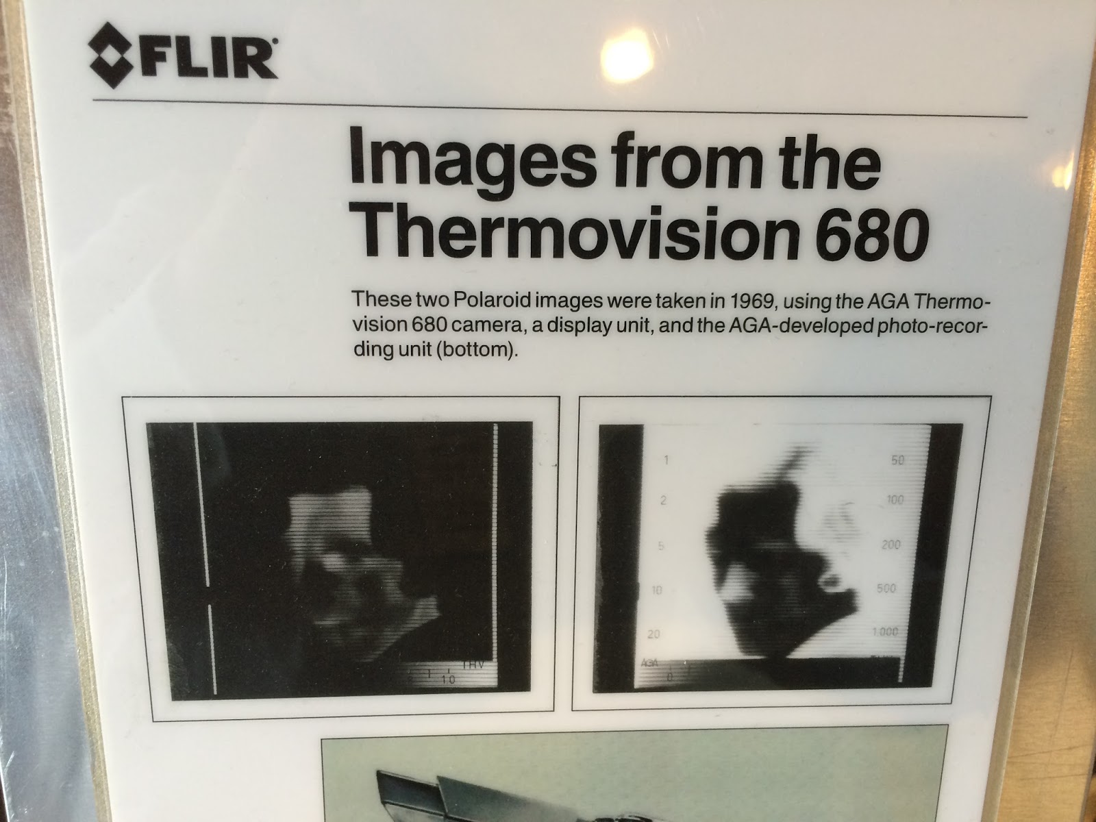
Throwback Thursday – Thermovision 680 Medical


Check these pictures out for #TBT; a Thermovision 680 Liquid Nitrogen cooled system circa 1968 that was utilized for medical applications.

Originally manufactured by AGA Infrared Systems of Sweden, the camera had interchangeable lenses and a Polaroid camera attachment that was used to capture the infrared images shown on a display unit (not seen here) as there was no on-board file storage.

The "Short Wave" model used a single InSb (Indium Antimonide) detector while the Long Wave version featured a HgCdTe (Mercury Cadmium Telluride) detector.


Monday, November 2, 2015

InfraMation 2018 - Call for Papers and Abstracts

InfraMation 2016 will be held in Las Vegas, Nevada, at the Rio All-Suite Las Vegas Hotel and Casino September 27-29, 2016, with a pre-conference training day on September 26. Join other thermal imaging experts to learn the latest thermal imaging techniques and applications, and make valuable connections!

The InfraMation 2016 Call for Papers is now open through February 5, 2016. FLIR Systems and the Infrared Training Center (ITC) are currently accepting 150-250 word abstracts of presentations and/or clinics to be delivered to InfraMation 2016 conference attendees. The audience will consist of more than 500 condition monitoring engineers, maintenance technicians, building inspectors, restoration contractors, research and science professionals, optical gas imaging specialists, and test and measurement buyers. Submit your abstract through this simple online form.

image

Benefits & Requirements

Why should you present at InfraMation 2016?

  • Qualify for a deeply discounted conference registration fee
  • Identify yourself as an infrared thermal imaging expert in your field
  • Earn valuable certification renewal credits
  • Further validate your expertise for clients and customers
  • Expand your professional and business referral network
  • Represent your organization on a big stage
  • Publish your paper on a searchable CD that every InfraMation attendee receives

InfraMation is the leading infrared training experience in the world. As thermal imaging becomes more mainstream, early adopters such as yourself will be sought out for your extensive knowhow and experience. Simply put: InfraMation is the place to get recognized!

The only "hard" requirements are that your paper be non-commercial in nature (for sponsorship or exhibition opportunities, click here) and submitted in English. Abstract approval is based on clarity, suitability, and technical merit of work.

Suggested Topic Areas

  • Buildings - Roofing Systems
  • Buildings - Water Ingress / Moisture / Remediation / Mold Testing
  • Buildings - Insulation / Air Leakage / Energy Loss
  • Buildings - Standards & Certification
  • Buildings - Pest Detection and Control
  • Condition Monitoring - Electrical Distribution - Indoor, Outdoor, Transmission, Distribution
  • Condition Monitoring - Mechanical Applications - Bearings, Gearboxes, Conveyors, Steam, Hydraulic
  • Condition Monitoring - Standards & Certification
  • Condition Monitoring - Petrochemical Applications
  • Business - Marketing/Sales/Pricing
  • Business - Program Management / Cost Avoidance / Cost Saving
  • Business - Safety
  • Research & Science Applications
  • Medical/Veterinary Applications
  • Optical Gas Imaging Applications
  • IR Report Preparation Techniques
  • NEW - Aerial Drone and UAV Applications / Techniques
  • Non-Destructive Testing - Material flaws, voids, etc.
  • Alternative / other Applications / Other Technologies

Wednesday, September 30, 2015

InfraMation 2016 - The Leading IR Training Experience

InfraMation, the leading IR training experience and thermal imaging conference, returns to Las Vegas and the Rio All-Suite Hotel and Casino September 26-29, 2016.  Registration is now available at www.inframation.org

The main conference will run Tuesday, September 27 through Thursday, September 29, with a pre-conference training day scheduled on Monday, September 26.  Join other thermography experts from around the world to learn the latest thermal imaging techniques and applications while making valuable connections!

And don’t just take our word for it…check out this video to see what past InfraMation attendees are saying about their experiences at the world’s largest conference for professional thermographers:


The best registration deal available for a limited time is the Platinum Package that not only includes full access to all four days of the event and conference meals, but also a FLIR C2 compact thermal imager, free ITC certification renewal, and entry into a drawing for a free FLIR E8 infrared camera.

The pre-conference training day on Monday, September 26, is a must for any thermographer looking to expand their knowledge in one of four available educational tracks that include two new certificate training areas: 

  • Optical Gas Imaging and Research & Science 
  • FLIR Tools Software and Thermography Inspections with UAVs 
  • Advanced Thermography for Condition Monitoring – Certificate Training 
  • Fundamentals of Thermography & Home Inspections – Certificate Training
More details coming soon including a Call for Papers for those who are interested in sharing their knowledge and experience with other industry professionals, plus sponsorship and exhibiting opportunities too.  Until then, follow ITC on Facebook (www.facebook.com/InfraredTraining) and Twitter (www.twitter.com/ITCInfrared) with the hashtag #inframation16 for the latest updates on InfraMation 2016.  See you in Las Vegas!

Tuesday, July 14, 2015

Live Webcast Schedule Continues Through September 2015

The Infrared Training Center is pleased to announce that a new round of live webcasts are now scheduled through September 2015.  These free webinars provide a valuable overview of thermal imaging and its many applications.  New topics for this quarter include using IR for HVAC applications and an introduction to the ResearchIR software program for thermography cameras. 

In addition, ITC now has 20 on-demand webinars available for viewing at any time including sessions in German and French with more to come throughout the rest of 2015.

Registration for all US-based live webcasts and on-demand webinars can be found at www.infraredtraining.com/webinars

Or head to http://www.irtraining.eu/en/webinars/webinars.html for more information on our Europe-based live webcasts and on-demand sessions.

New Live Webcasts: July – September 2015

Infrared Thermography Basics
Friday, July 24

Ask the Expert: IR & Electrical Safety

Friday, July 31

FLIR Tools Software Basics

Friday, August 7

FLIR Tools+ Advanced Software

Friday, August 7

HVAC and IR Inspection Basics

Friday, August 14

Ask the Expert: Capturing Great Thermal Images

Wednesday, September 2

Introduction to ResearchIR Software for Thermography Cameras

Thursday, September 10

IR Basics for Home Inspectors

Thursday, September 10

Introduction to IR for Mechanical Applications

Friday, September 25