Here’s a video with Tom O’toole of FLIR Systems and Flemming Lund, a certified Energy Auditor & Home Inspector, talking about the tools used in the various phases involved in a home energy audit.
Infrared Training Center

Showing posts with label IR camera. Show all posts
Showing posts with label IR camera. Show all posts
Wednesday, January 10, 2018
FLIR Home Energy Audit Tools
What tools do Home Energy Auditors and Home Inspectors use? Shopping for
the right Home Energy Auditor or Home Inspector can be a timely
process. Beyond their certifications and experience, you should also
consider the types of tools they use to perform their tasks.
Here’s a video with Tom O’toole of FLIR Systems and Flemming Lund, a certified Energy Auditor & Home Inspector, talking about the tools used in the various phases involved in a home energy audit.
Here’s a video with Tom O’toole of FLIR Systems and Flemming Lund, a certified Energy Auditor & Home Inspector, talking about the tools used in the various phases involved in a home energy audit.


Monday, November 13, 2017
Emissivity and Reflected Temperature
What should I enter for my emissivity and reflected temperature values?
First, ask yourself how are you using your thermal imager? Is it to identify thermal patterns or measure temperatures? If you are simply trying to locate thermal patterns such as missing insulation or air leakage in a building (what is called qualitative thermography) measuring an exact temperature really isn’t necessary. In these situations, leave the values at their default settings (typically 0.95 for emissivity and 68F/20C for reflected temperature) and go for it.
If you need to measure an exact temperature of a motor or a bearing (what is called quantitative thermography) then correctly setting emissivity and reflected temperature is a must to get the most accurate reading. Doing so, however, should only be attempted by properly trained and certified thermographers…those who are the most qualified to measure temperatures with an infrared camera.
Thermography Certification Dates and Locations
What Is the Best Approach Until Then?
We recommend using the following basic guideline for taking simple measurements. Know there are many other factors you will need to consider which are covered thoroughly in all ITC training classes. Until then, to get started, let’s first define emissivity and reflected temperature.
What is Emissivity?
Emissivity is how efficiently an object radiates heat. It’s defined as the ratio of infrared energy emitted by the object, compared to that emitted by an ideal blackbody, if both are at the same temperature. It is represented as either a percent or a decimal.
Surfaces exhibit emissivity values ranging anywhere from 0.01 to 0.99. A highly polished metallic surface such as copper or aluminum are often below 0.10 and are practically an infrared mirror. Heavily oxidized metallic surfaces will have a much higher emissivity (0.6 or greater depending on the surface condition and the amount of oxidation). Most flat-finish paints are around 0.90 (in long-wave infrared) while human skin and water are about 0.98.
What is Reflected Temperature?
Reflected temperature (also known as background temperature or Treflected) is any thermal radiation originating from other objects that reflects off the target you are measuring. To properly obtain an accurate surface temperature reading with thermal imaging, this value (along with that of emissivity) must be quantified and programmed into the camera’s “Object Parameters” (or corresponding software if processing a saved image). This is used so that the software can compensate for, and ignore, the effects of this radiation as it does not relate to the actual surface temperature of the object you are measuring.
For higher emissivity objects, reflected temperature has less influence. For lower emissivity objects, however, it’s a critical factor that *must be* understood carefully! As emissivity decreases, what you are measuring (and seeing thermally) is coming more from the surfaces of surrounding objects (including the camera and operator), not the target you are inspecting.
How to Take a Basic Temperature Measurement
The easiest way to get an accurate measurement is to modify the surface with a material that has a high, known, and consistent emissivity value. Standard electrical tape, with its emissivity of .95, is one such item that works well for this purpose.
If the surface is safe to touch, simply adhere a piece of electrical tape to that object and set the camera’s emissivity value to 0.95. Next set the reflected temperature to an appropriate value for the environment. A stable, room temperature environment will provide the best results. If you’re still unsure what that value might be, we strongly suggest a minimum of Level I Certification training to understand this concept further.
Next, measure the temperature of the tape with the camera’s spot meter or other measurement tool, being sure that the spot meter’s circle (called the reticle) is filled completely by the target. IMPORTANT SAFETY NOTE: This “tape method” should *only be utilized* on stationary surfaces that can be accessed safely and are okay to touch. If attempting this type of measurement on an electrical component, the circuit *must* first be shut off and locked-out/tagged-out before proceeding.
What About Measuring Emissivity and Reflected Temperature on Other Surface Types?
For other surface types, or if temperature measurement accuracy on a variety of other objects is important for you and your inspection program, a minimum of a Level I Thermography Certification Training course is required. Level I will teach you how to correctly adjust emissivity and reflected temperature on a variety of other components including those that are electrically energized or are difficult to access. Attendees will learn about the proper procedures needed to evaluate both to ensure thermographers are getting the most accurate temperature readings with their thermal imager.
To learn more about these certification classes, as well as upcoming training dates and locations, please visit the Infrared Training Center online at http://www.infraredtraining.com
First, ask yourself how are you using your thermal imager? Is it to identify thermal patterns or measure temperatures? If you are simply trying to locate thermal patterns such as missing insulation or air leakage in a building (what is called qualitative thermography) measuring an exact temperature really isn’t necessary. In these situations, leave the values at their default settings (typically 0.95 for emissivity and 68F/20C for reflected temperature) and go for it.
If you need to measure an exact temperature of a motor or a bearing (what is called quantitative thermography) then correctly setting emissivity and reflected temperature is a must to get the most accurate reading. Doing so, however, should only be attempted by properly trained and certified thermographers…those who are the most qualified to measure temperatures with an infrared camera.
Thermography Certification Dates and Locations
- Training Dates and Locations in the US and Canada: http://www.infraredtraining.com/schedule
- Training Dates and Locations in Europe, Middle East and Africa: http://www.irtraining.eu
- Certification training from the Infrared Training Center (http://www.infraredtraining.com) teaches you the techniques required for determining these values and will provide a complete understanding of temperature measurement and heat transfer.
What Is the Best Approach Until Then?
We recommend using the following basic guideline for taking simple measurements. Know there are many other factors you will need to consider which are covered thoroughly in all ITC training classes. Until then, to get started, let’s first define emissivity and reflected temperature.
What is Emissivity?
Emissivity is how efficiently an object radiates heat. It’s defined as the ratio of infrared energy emitted by the object, compared to that emitted by an ideal blackbody, if both are at the same temperature. It is represented as either a percent or a decimal.
Surfaces exhibit emissivity values ranging anywhere from 0.01 to 0.99. A highly polished metallic surface such as copper or aluminum are often below 0.10 and are practically an infrared mirror. Heavily oxidized metallic surfaces will have a much higher emissivity (0.6 or greater depending on the surface condition and the amount of oxidation). Most flat-finish paints are around 0.90 (in long-wave infrared) while human skin and water are about 0.98.
What is Reflected Temperature?
Reflected temperature (also known as background temperature or Treflected) is any thermal radiation originating from other objects that reflects off the target you are measuring. To properly obtain an accurate surface temperature reading with thermal imaging, this value (along with that of emissivity) must be quantified and programmed into the camera’s “Object Parameters” (or corresponding software if processing a saved image). This is used so that the software can compensate for, and ignore, the effects of this radiation as it does not relate to the actual surface temperature of the object you are measuring.
For higher emissivity objects, reflected temperature has less influence. For lower emissivity objects, however, it’s a critical factor that *must be* understood carefully! As emissivity decreases, what you are measuring (and seeing thermally) is coming more from the surfaces of surrounding objects (including the camera and operator), not the target you are inspecting.
How to Take a Basic Temperature Measurement
The easiest way to get an accurate measurement is to modify the surface with a material that has a high, known, and consistent emissivity value. Standard electrical tape, with its emissivity of .95, is one such item that works well for this purpose.
If the surface is safe to touch, simply adhere a piece of electrical tape to that object and set the camera’s emissivity value to 0.95. Next set the reflected temperature to an appropriate value for the environment. A stable, room temperature environment will provide the best results. If you’re still unsure what that value might be, we strongly suggest a minimum of Level I Certification training to understand this concept further.
Next, measure the temperature of the tape with the camera’s spot meter or other measurement tool, being sure that the spot meter’s circle (called the reticle) is filled completely by the target. IMPORTANT SAFETY NOTE: This “tape method” should *only be utilized* on stationary surfaces that can be accessed safely and are okay to touch. If attempting this type of measurement on an electrical component, the circuit *must* first be shut off and locked-out/tagged-out before proceeding.
What About Measuring Emissivity and Reflected Temperature on Other Surface Types?
For other surface types, or if temperature measurement accuracy on a variety of other objects is important for you and your inspection program, a minimum of a Level I Thermography Certification Training course is required. Level I will teach you how to correctly adjust emissivity and reflected temperature on a variety of other components including those that are electrically energized or are difficult to access. Attendees will learn about the proper procedures needed to evaluate both to ensure thermographers are getting the most accurate temperature readings with their thermal imager.
To learn more about these certification classes, as well as upcoming training dates and locations, please visit the Infrared Training Center online at http://www.infraredtraining.com
Thursday, October 26, 2017
Windshield Glass Reflections - How to Remove Them
by Bernie Lyon, Gary Orlove, and Jason Gagnon
"I do a lot of windshield defrost testing at different temps. And I wonder is there any way that can keep from having the camera and myself reflected back into the images."
Glass is about 15% reflective in the 8-12 micrometer waveband. If you are directly facing the windshield, you will inevitably get a reflection of yourself and the camera. I'm sure you have seen this.
One option is to change the angle at which you are observing the windshield, see the image below. If you are at point A, you and the camera will be reflected. If you are at point B, the camera will reflect whatever is above the vehicle, represented by C.

If there are hot objects or objects with temperature variations above the vehicle, that might make things worse. They will reflect off of the glass. If possible, you could place a high emissivity piece of material above the windshield so that all reflections off of the glass are uniform. A large piece of cardboard or a blanket might do well.
This way, you will observe only temperature changes, not patterns due to non-uniform reflections.
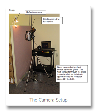
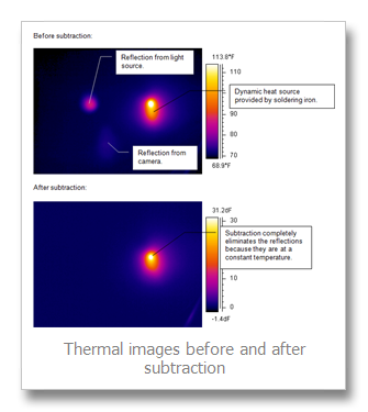
Another option is to use image subtraction techniques (you will have to have software which supports this, such as FLIR ThermaCAM Researcher).
- Take an image before running the defroster.
- Then save images as you normally would.
- Subtract the first image from the succeeding ones. The resulting image will show only changes in temperature and the reflections will have been eliminated. See the series of images below:

Thursday, October 12, 2017
Use of the Wedge Method for Emissivity and Reflection Independent Temperature Measurement
By: Ralph Rudolph
R. Rudolph Consulting LLC @ www.temperatureconsultant.com
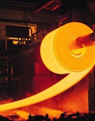
Blackbody conditions exist for a cavity if and only if all sides of the cavity are at the same temperature. If the roll being used has a very low thermal mass (heats up easily) and there is a large wrap around the roll and sufficient strip tension to allow heat transfer to occur between the strip and the roll, then the roll will heat up to near strip temperature over a time period, but because the roll has natural convection, conduction and radiation losses, the roll can never quite reach the strip temperature. Emissivity never reaches 1.0. It should be obvious that if the strip abruptly changes temperature, which can happen with strip thickness or furnace temperature changes, it will take time for the roll to change temperatures. Heat transfer between the two can take quite a while during which time the temperature reading from the wedge system will be quite inaccurate.
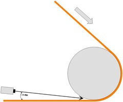
Figure 1.
So, if a system is designed well, with a major roll wrap, low thermal mass roll, sufficient strip tension and steady long term operation (no major changes in strip temperature), this method can work as claimed (except that emissivity must be set somewhat lower than 1.0 to compensate for the roll being at a slightly lower temperature than the strip).
Given human nature, however, I’ve seen numerous instances where folks have not understood why the wedge method can work and who have misapplied it. Believe it or not, I’ve seen an instance where a so-called wedge method has been applied with zero roll wrap, with the strip simply passing over a support roll. And this system was (unfortunately) designed by the equipment provider who should have known better. I would guess that a majority of wedge method applications that I’ve seen have been poorly designed, with little attention paid to the amount of roll wrap or roll material and with little understanding of what occurs during changes in strip temperature.
There is a modification to the wedge method that can provide a significant improvement: Mount a second Radiation Thermometer to monitor roll temperature and compare this reading to that of the wedge RT. Using a PC with input and output cards (and most any older PC will work), abrupt deviations between the two readings which occur as strip temperature changes can be used to correct for errors. If accuracy is desired, it’s well worth the extra expense. You get what you pay for.
Wednesday, September 13, 2017
Getting Started with R&D Thermography Online Course
 Video tutorials on IR Camera Properties and getting started with ResearchIR. For any SC camera including A300, A320, SC645, SC6000, SC6700, and SC7000, SC8000 cameras. There is NO CHARGE for this FREE course.
Includes information on:
- Camera Technology
- Cooled vs Uncooled Thermal Cameras: Field of View
- The difference between cooled & uncooled thermal detectors?
- Cooled vs Uncooled Thermal Cameras: Speed
- Cooled vs Uncooled: Sensitivity
- FLIR ResearchIR Max
- Connecting to the Camera
- Image Enhancement
- Image Subtraction
- Recording Data
- Triggering
- Super Framing
- Analysis Tools
- Analysis Charts
- Measurement Functions
- Sharing Data
- File Extraction Tool
- FLIR ResearchIR and MATLAB
- FLIR Thermal Face Detection and Tracking in Matlab
- Opening FLIR Movies with Matlab Software
- Connecting FLIR Systems GigE Cameras to MATLAB
- Applying MATLAB Filters in FLIR ResearchIR Max Software
Thursday, September 7, 2017
IR finds Yellow Jackets Nest in House
by Sanin Mulic, Barber Foods
After attending my level one instruction during the week, and ITC wetting my appetite for thermal imaging, I returned home with my company's P-65 camera. I decided to scan my own house to practice what I was taught all week. All looked good until I went upstairs and noticed a bright spot on the inside wall. I took several images of the spot and come Monday, I talked to two level 2 associates about what I had found. There were several possibilities and I was told to take several more shots at different times to see if it moved or varied in temperature. When we found it never moved I suggested that it might be insects (wasps, hornets, etc.) and talked with one of the other thermographers who would bring in a stethoscope to see if I could hear them before opening up the wall.
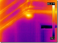

Thermal image of the wasp nest (left).
I couldn’t wait, so that night armed with a drill, a can of flying insect killer, and the enthusiasm of a new thermographer, I went up to the room; my pet cat, who loves to lay in the window there, had to investigate with me too. I approximated where the hotspot was and drilled a 1/8 “ hole through the wall board. As I removed the drill bit, about 8 to 10 yellow jackets came charging through the hole and I started to spray the bug spray at the hole. By this time, the yellow jackets were in an attack mode and I started to swing at them in defense. Out of the corner of my eye I saw my cat speeding to the door with his tail bigger than I have ever seen it. I finally killed the last one, sprayed about 1/3 of the can, and plugged the hole; but not before being stung twice. I went outside and saw a swarm just outside the window. I drilled a second hole a few inches above it and knowing what was going to follow, I had the spray ready to go as soon as the drill came out. I sprayed about 1/3 of the can and then plugged the hole. I returned several hours later and the swarm was gone. I climbed a ladder and found a small hole where they were coming and going. I plugged that from the outside. As I came back inside I saw my cat peaking from around the door as if to ask “Is it safe to come out now?”
After a few days I took another thermal image and there was no evidence of the yellow jackets remaining. I submitted this investigation as my level one field report and it passed, but the memory of this initial experience will last a long time (the cat won’t forget it either!)
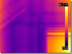
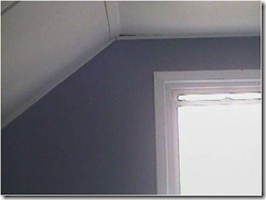
No wasps after removal.
Wednesday, July 8, 2015
New Online Course: FLIR Cx Operation Basics

We will discuss the controls of the camera as well as the user interface, and show you how to operate your camera and your report and analysis software.
Who should take this course: This course is intended for users of the FLIR Cx camera or anyone interested in purchasing one.
Prerequisites: No prior knowledge of thermography or infrared cameras is assumed.
Availability: This course is an on-demand self paced web based training course available 24 hours a day, 7 days a week. You can begin as soon as you enroll.
Course Homepage
Monday, April 13, 2015
ThermalSpeak – building efficiency and thermal bridging
by Jay Bowen
BPI Energy Analyst
ASNT NDT Level 3 Thermographer
Building conversations in training this week brought up the subject of thermal bridging in the structure. Defined by a material of less insulation or greater conductivity. This material bridges or short circuits the better insulation and reduces its effectiveness. This reduces the overall R value rating of the whole assembly. The following website, http://web.ornl.gov/sci/roofs+walls/AWT/home.htm , addresses this whole wall rating concept. This isn’t a debate of test methods or approaches. It is enough to say that anything put in the wall that reduces the energy of that wall should be addressed in the construction process.
My input on this subject is finding these, before construction begins and discussion with a builder, methods to reduce or eliminate these bridges. Verification of the design or confirmation as building progresses would be where a thermographer can enter the process and provide proof that the building project has conformed to this concept of design.
The images from a qualified thermographer provide detailed analysis of construction detail typically hidden from the inspectors or builders.
Taking a set of images to compare this approach can clearly see the advantage of reducing the vertical framing typical of stick built construction. Even the wide wall of 2x6 framing to increase the side wall dimensions for increased insulation. This is an increase in the R value but the thermal bypass of the stud is still there.
|
|
|
| Using SIP to reduce bridging | Standard stick frame wall |


Looking at a SIP wall can visualize the reduction in the bypasses by reducing the vertical framing. The corners and joints are still present but can be reduced by the same methods of stick built using exterior insulated sheathing.
Making the bridge elimination or reduction a conscious thought in the whole building process can have substantial rewards in energy saving in the home.
Monday, February 2, 2015
Inspecting Steam Valves with Thermography
by Ron Lucier, ASNT NDT Level III
They are several types of steam valves:
Isolation Valves
Steam is hot and many valves and lines are insulated. This is a problem for inspection. I used to have holes in insulation cut anywhere from 10 to 16 “pipe diameters” away from the valve, on the bottom of the pipe and use high temp black paint. I would also cut a hole in a convenient location upstream of the valve and within a day of startup establish a baseline.
They are several types of steam valves:
- Isolation Valves
- Control Valves
- Non-Return Valves
- Safety Relief Valves
Isolation Valves
Steam is hot and many valves and lines are insulated. This is a problem for inspection. I used to have holes in insulation cut anywhere from 10 to 16 “pipe diameters” away from the valve, on the bottom of the pipe and use high temp black paint. I would also cut a hole in a convenient location upstream of the valve and within a day of startup establish a baseline.

Wednesday, August 6, 2014
InfraMation Call for Papers. Get Your Abstracts Ready!
 InfraMation 2015 is now less than a year away and there’s no time like the present to seriously consider sharing your expertise on the issues facing today’s thermography professionals. Clinics, presentations, and poster sessions all originate with you so FLIR and ITC are calling for your papers now for InfraMation 2015.
We are thrilled to be bringing the conference to the heart of Music City in Nashville, Tennessee. Along with the opportunity to help others succeed in building diagnostics and condition monitoring infrared, those with valuable insight into optical gas imaging and research and science thermography, are strongly encouraged to participate!
Start here to submit your abstract: www.inframation.org/papers
If you haven’t submitted an abstract before, then I hope you’ll do so this year. Here are just some of the benefits of being a presenter or instructor at InfraMation:
- Qualify for a deeply discounted conference registration fee and/or honorarium
- Identify yourself as an infrared thermal imaging expert in your field
- Earn valuable certification renewal credits
Whatever your thermal imaging know-how, there’s an interested audience at InfraMation. From building investigations to electrical and mechanical monitoring to R&D and OGI to thermography program management and marketing, attendees are always riveted and appreciative.
Not planning to submit an abstract this year? Then be sure to register for the conference right away to take advantage of the incredible Early Bird Special pricing still available.
Friday, July 18, 2014
Online Thermography Basics Course Updated
Description
This course is a more advanced introductory course in thermography and serves as an excellent, and recommended, addition to the infrared camera basics and infrared basics courses. Thermography involves more than just learning how to use an infrared camera. IR science, heat transfer, thermal tuning, and application knowledge are all essential subjects a thermographer must understand in order to properly interpret an image.This course will give the learner the basic information to understand these concepts.
Accreditation: 2.5 ITC Certification Renewal Credits, 2 RCI Continuing Educational Hours (CEHs)
Note: You can stop the course and re-enter exactly where you left off at a later time or day, you don't have to complete the course in one sitting.
Link to the course
Tuesday, July 8, 2014
IR on Electric Motors: Great for the Plant…and at Home Too!
It’s no secret that infrared can be used to diagnose problems with electric motors in industry, but residential applications? As ITC Instructor Ron Lucier recently discovered, possibilities exist at home as well, this one involving his pool pump motor:
Returning from a recent Level III class in Nashua I heard an awful noise in my backyard when I stepped out of my car. Pretty quickly I determined it was my pool pump motor (1 horsepower). What a racket. Sounded like just a bearing so I brought out my trusty vibration acceleration detector: a screwdriver. Measuring at each bearing of the motor and the pump I didn’t feel very much. However, I noticed a black spot on the side of the gold painted motor. It was time to get out the IR camera: my brand new FLIR T650sc.
I would find out the next day that the long wave emissivity for this paint is 0.91 so making the correction the hot spot was about 201 F! Good thing that I didn’t try to touch it!

Monday, February 3, 2014
InfraCanada/InfraQuebec 2014 - Call for papers
 ITC and FLIR Canada are proud to re-institute the Infrared and Maintenance conferences that have been on hiatus for the last couple of years – InfraCanada and InfraQuebec. This year’s conferences will be held in September and October and the venues are: Banff (Alberta), Hockley Valley Resort (Ontario), Mount Tremblant (Quebec) and Moncton (New Brunswick). We are currently looking for presenters for each of the conferences.
Why Present? As a successful user of the Infrared technology, you can share your knowledge and findings with other infrared users or potential users. Educating other interested parties will certainly enhance the Infrared community. Interacting with colleagues and peers may generate possible additional consulting opportunities. Presenters also earn valuable ITC recertification credits to maintain their current ITC certification level. Registration cost for the day you present will be reduced.
Some examples of subject matter for presentations are but not limited to:
- Condition Monitoring
- Building Applications
- Automation
- Science
- Fugitive Emission Detection
- Animal/Veterinary
- Medical
- Infrared Complimentary Non-Destructive Testing Tools
Please forward your presentation overview to Paul.Frisk@flir.com by March 15th, 2014.
More details about the conferences to follow in future newsletters.
Friday, January 10, 2014
New Online Course: FLIR K Series Basics
A tutorial on the basic operation of FLIR K Series Infrared Cameras for Fire Fighters in English, French, and German. This course is offered at no charge.
Course Homepage
Wednesday, October 2, 2013
MSX Explained - in Plain English
 Have you ever wished you could have a high fidelity thermal image, but also be able to read labels and see discrete details not shown in the thermal image?
Well now you can, with a new technology called MSX.
MSX stands for Multi Spectral Dynamic Imaging, an exclusive image enhancement technology now available on several infrared cameras. This new technology is based on a unique onboard processor that provides extraordinary thermal image details in real time. MSX incorporates real-time thermal video augmented with visible spectrum definition. It produces exceptional thermal clarity to highlight exactly where the problem is. MSX ensures easier target identification without compromising radiometric data. The quality of the thermal images is excellent. There is almost no need any more for a separate digital image; MSX embosses digital camera detail onto thermal video and stills.
How does it work?
An onboard processor continually processes the visual channel and extracts only the visual detail from the visible channel. That visual detail is then added to the thermal image information. Unlike many thermal fusion technologies, the thermal information is not diluted at all, it is just augmented with visual detail not apparent in the thermal image. The result is an incredibly robust and fully radiometric thermal image displaying details and making it easy to know what is being viewed and where problems lie. See this video.
MSX Explained
Thursday, April 4, 2013
Using a Wide Angle Lens as a Macro or Close Up Lens
 Some thermographers are surprised to learn that many wide angle lenses can be used for high magnification work. After all, the wide angle lenses have a larger IFOV and IFOV footprint, so how can they be used for small targets effectively?
Here is a typical example for a FLIR E60 camera (320 x 240 resolution):
| Lens FOV | IFOV (mrad) | IFOV footprint at 19.7” Working Distance |
| 25° x 19° | 1.36 | 0.03” |
| 45° × 33.8° | 2.59 | 0.05” |
The specs above don’t indicate that a wide angle lens is any better, in fact it has a larger footprint. So what gives?
Take a look at the thermograms below:
 | Here is a thermogram of a ruler taken with the standard 25° lens at its closest focus distance of 9.2”. Note how the scribed lines on the 100ths scale are fuzzy and merge together. The horizontal FOV is about 3”. This indicates that items this small cannot be resolved using this lens. |
 | I have enlarged the 25° image to illustrate the blurred lines on the scale. |
 | Here is the same ruler taken with a 45° lens. The scribed lines can clearly be seen and differentiated. The horizontal FOV is about 1.5”. What’s the secret? The 45° lens can be focused much closer to the target (1.2”). Hence it effectively can resolve smaller targets. |
Does a wide angle lens work as well as a dedicated close up lens? No, of course not. You might notice that the sharpest areas are in the middle of the image. A dedicated optic for close up work would be designed to reduce this effect while achieving higher magnification.
But as a dual purpose optic, when you need to do some close up work, a wide angle lens is pretty handy.
Here are some images from a FLIR P640 for comparison.


Wednesday, May 2, 2012
IR InformIR Blog Enhancements
I have added a few enhancements blog readers should appreciate.
 A search box has been added so you can easily search the blog for the content you are looking for.
 The blog can now be easily translated into one of 54 different languages, everything from Afrikaans to Yiddish. Just use the drop down menu on the right and choose your language!
 An easy “follow by email” tool has been added which makes it easier than ever to get new blog content sent to your email box automatically and right away.
Enjoy!
Wednesday, February 8, 2012
Measuring Body Temperature with an Infrared Camera
by Mikael Cronholm and Gary Orlove
From a biological standpoint, human beings are so called warm blooded animals. That means that we maintain a fairly constant body temperature, regardless of the surrounding temperature. The term body temperature (that we compare with when we decide whether a person has a fever or not) refers to the inside temperature, or core temperature of the body. The outside of the body is nearly always colder. It must be, because as we convert the energy from our food when we do work, we also produce heat. That heat has to go somewhere and if the outside and inside temperatures were the same, no heat transfer would be occurring.
None of us have a constant metabolism, or energy conversion, over time. It varies with our activity level. That means that the amount of heat we need to lose also changes with time. Our surrounding temperature also changes up and down, which means that sometimes we need to conserve heat and sometimes we need to increase the cooling by increased evaporation of liquid, we start to sweat more. Sweating is something we always do, just more or less depending on the situation.
To be able to use non-contact measurement for fever screening purposes, we need to find a point on the outside of the body that is close to the inside temperature – our “body temperature”. Because the outside is colder, and varies from place to place on the body, it is obviously the highest temperature on the outside of the body that is also the closest to the inside temperature. So we want to look for a warm spot on the outside.
Wednesday, January 4, 2012
Analyzing Building Images Acquired at Different Times
A camera user writes:
"I find that images taken of the same structure, not much separated in time, sometimes look very different. This poses a problem for me as I’m trying to compare the heat images of different houses (to detect homes that need weatherization). Presently I’m not confident that images of two homes reflect actual differences in the structures, or are caused by minor environmental changes or even by artifacts in the photography. Here is an example.
Attached are two nighttime images of the front of my house, which faces east. IR0310 was taken at 10:40 PM, IR0408 at 11:11 PM. (The clock on the camera is two hours fast.) It was a cold night with little temperature change over the half hour between pictures. The house thermostat was constant.
I've set the palette and temperature range to give me good differentiation of houses along the street. I took the first image of my house as I began imaging houses on my street, and I took the second image when I finished the street scan.
I am surprised, first, that my house looks so different in the two images. And second, that the outside looks warmer in the later image. If anything, I'd have expected the outside to have cooled.
Glad for any interpretation of this. Needless to say, with this kind of variation on a single house, it is hard to get good images for comparing houses. "


Tuesday, June 21, 2011
Online Thermography Training Courses
ITC has made the following courses available to IR camera users.
WEB-TH10 Thermography Basics This course is a primer or first course in thermography and serves as an excellent, and recommended, addition to the infrared camera basics operation courses. Thermography involves more than just learning how to use an infrared camera. IR science, heat transfer, thermal tuning, and application knowledge are all essential subjects. 2 ITC Certification Renewal, 2 RCI Continuing Educational Hours (CEHs). This course is FREE.
WEB-TH20 Introduction to Indoor Electrical Surveys using IR Thermography This introductory course is designed to give you a straight forward explanation of how Infrared technology fits in the indoor electrical inspection industry. This course is a replay of a webinar session hosted by an Infrared Training Center instructor and webinar director. This course earns 1 ITC Certification Renewal Credit.
WEB-TH25 Introduction to Outdoor Electrical Surveys using IR Thermography
This introductory course is designed to give you a straight forward explanation of how Infrared technology fits in the outdoor electrical inspection industry. This course is a replay of a webinar session hosted by an Infrared Training Center instructor and webinar director. This course earns 1 ITC Certification Renewal Credit.
WEB-TH30 Introduction to Residential Energy Audits using IR Thermography This introductory course is designed to give you a straight forward explanation of how Infrared technology fits into the residential energy auditing industry. This course earns 1 ITC Certification Renewal Credit. UPDATED February 18, 2011.
WEB-TH10 Thermography Basics This course is a primer or first course in thermography and serves as an excellent, and recommended, addition to the infrared camera basics operation courses. Thermography involves more than just learning how to use an infrared camera. IR science, heat transfer, thermal tuning, and application knowledge are all essential subjects. 2 ITC Certification Renewal, 2 RCI Continuing Educational Hours (CEHs). This course is FREE.
WEB-TH20 Introduction to Indoor Electrical Surveys using IR Thermography This introductory course is designed to give you a straight forward explanation of how Infrared technology fits in the indoor electrical inspection industry. This course is a replay of a webinar session hosted by an Infrared Training Center instructor and webinar director. This course earns 1 ITC Certification Renewal Credit.
WEB-TH25 Introduction to Outdoor Electrical Surveys using IR Thermography
This introductory course is designed to give you a straight forward explanation of how Infrared technology fits in the outdoor electrical inspection industry. This course is a replay of a webinar session hosted by an Infrared Training Center instructor and webinar director. This course earns 1 ITC Certification Renewal Credit.
WEB-TH30 Introduction to Residential Energy Audits using IR Thermography This introductory course is designed to give you a straight forward explanation of how Infrared technology fits into the residential energy auditing industry. This course earns 1 ITC Certification Renewal Credit. UPDATED February 18, 2011.
Subscribe to:
Posts (Atom)